MAGMA
Magma
Inject molten plastic into your prints to knit the layers together.
Magma is a fork of OrcaSlicer. It adds new infill types (Triangle, Rectilinear, and Tri-hex cells) that build sealed vertical U-shaped channels inside your part, then injects plastic into them mid-print using the printer’s nozzle. The goal is to fix FDM Z layer weakness by truly printing in 3D.
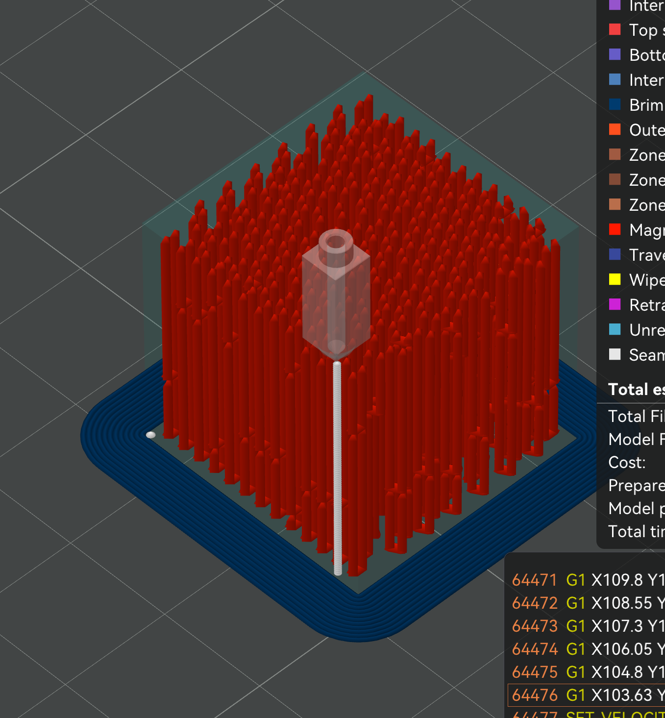
The nozzle drops into a channel, extrudes a column of plastic, lifts, and moves to the next. Every red column is one injection.
Status: It works in the slicer. I have not gotten a clean physical print yet. This is an open experiment, and I want testers with better hardware than mine. (Bug reports go to this fork, not the upstream OrcaSlicer repo.)
The problem
FDM parts are strong in XY and weak in Z. Bonding weakness on the layer lines results in parts that are much weaker and more brittle compared to injection molded ones. Magma attempts to finally solve this by injecting into U-shaped vertical channels to “knit” the part together vertically in the Z plane.
How it works
Magma replaces normal infill with a lattice of hollow channels — cells can be triangles, squares, or a hexagon-and-triangle mix, depending on which Magma pattern you pick. A solver pairs each channel with one of its shared-edge neighbors and cuts a small window between them at the bottom, making a vertical U. During the print, the nozzle drops into one side of the U, injects plastic under pressure, and it flows down, through the window, and up the other side. Air escapes out the top. It is a tiny version of injection molding. With tubes injected as they reach their computed height during the print.
One paired cell pair, vertical cross-section:

   Before injection:        After injection:

     ┌───┬───┐                ┌───┬───┐
     │   │   │                │███│███│
     │   │   │                │███│███│
     │   │   │      →         │███│███│
     │   │   │                │███│███│
     │   │   │                │███│███│
     │       │                │███████│   ← continuous through window
     └───────┘                └───────┘

  Two adjacent triangle      Injection fills both
  cells sharing a wall,      cells in a continuous
  with a "window" gap at     U-shape, mechanically
  the bottom.                interlocking with the
                             surrounding lattice.
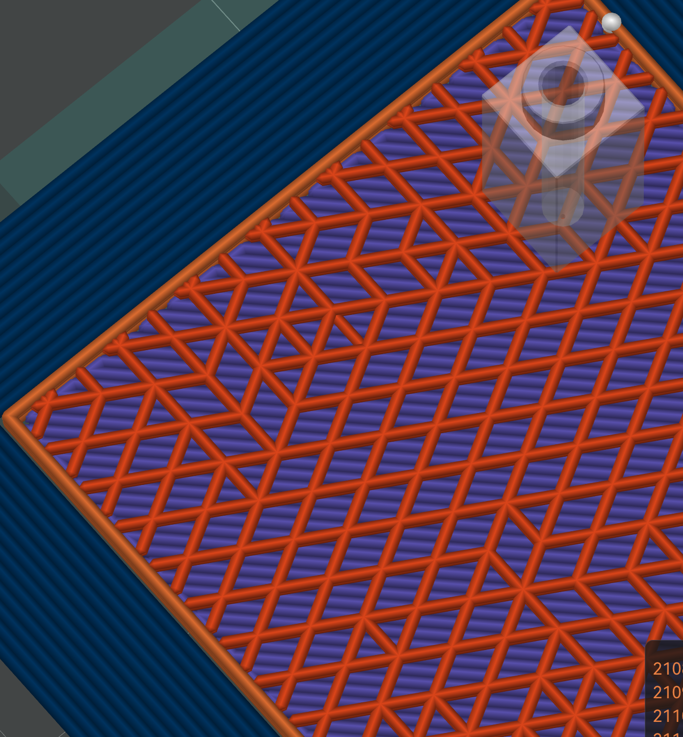
Orange is the Magma zone. The hexagonal gaps are windows, where channel pairs connect so plastic can flow from one tube into its partner.
Every paired cell has a gap in its shared wall. Plastic injected into one tube flows through and fills its U-tube partner.
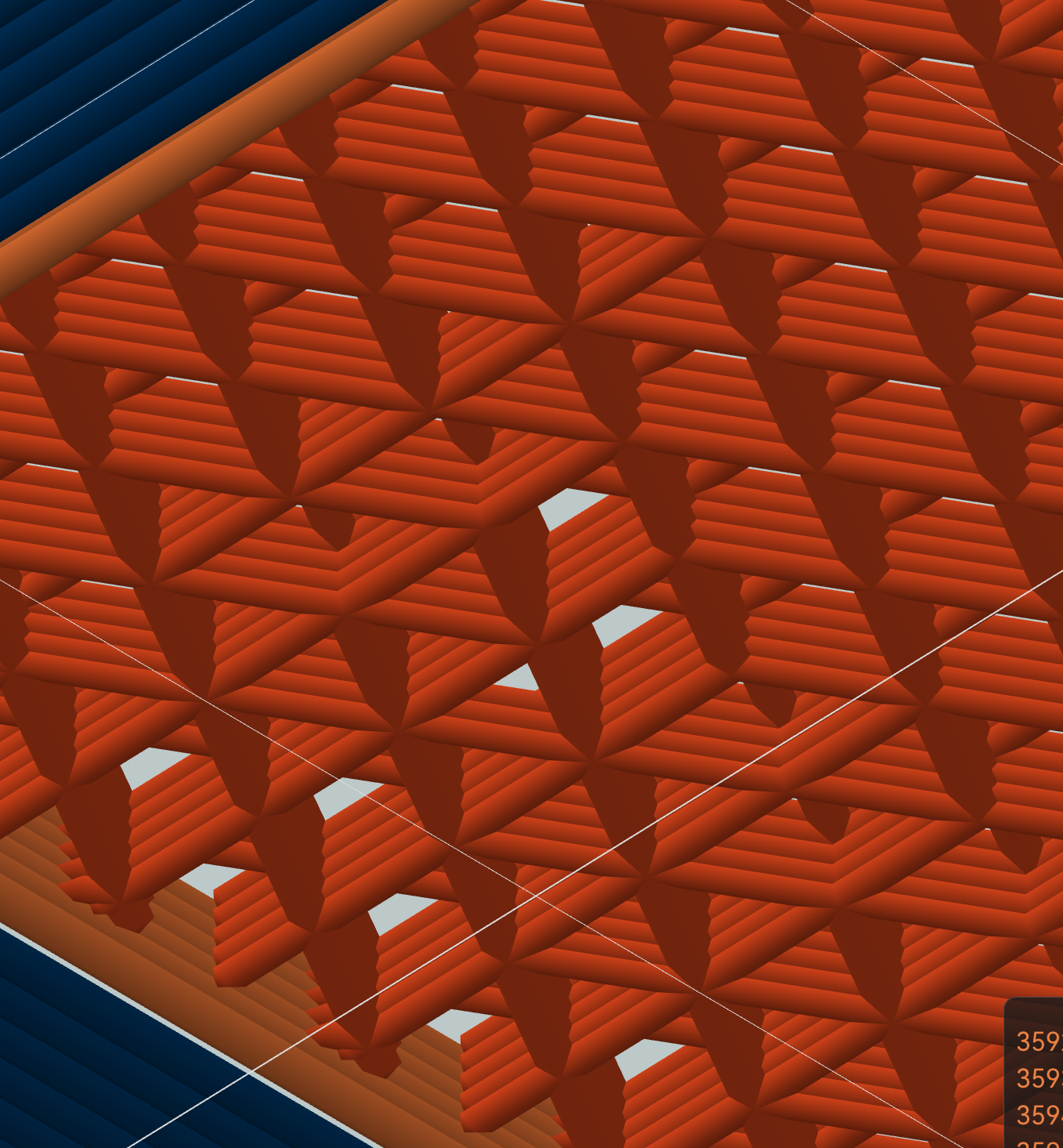
The solver also staggers the tube ends so neighboring tubes do not all start and stop on the same layer. That knits the part across Z instead of stacking weak seams. Slice anything with Magma infill, hide line types except injection in slicer preview, and you can see the knit for yourself.
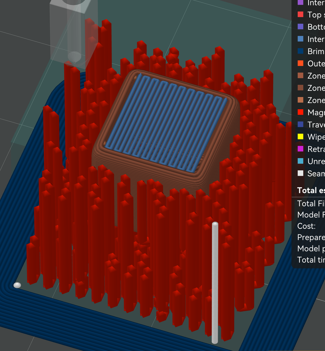
Red Magma tubes form the outer reinforcement zone around a solid blue inner zone. The cheap inner zone can use any normal infill.
What happened when I tested it
I ran about a hundred prints on an ancient clunky Ender 3. The slicer side works end to end. I haven’t gotten a clean print yet though.
Observations
Tube top compromise
The top of the tube nearly always melts while injecting, compromising the seal that allows plastic to be injected into the tube. This could be remedied with a higher injection speed, lower viscosity injection material, better cooling, a film or cover or heat break in the nozzle to prevent heat flow into the print when the nozzle contacts the top of the cells. Or by injecting something that’s not a thermoplastic, like resin or silicone. A related failure — neighbouring cells melting each other when injected back-to-back — is what the Spread heat injection order (magma_injection_ordering) is for: it spaces nearby injections out in time so the heat dissipates between them.
Injection flow limitations
Plastic viscosity limits max tube height. Could be remedied with lower viscosity plastic, higher injection temps, better nozzle seal (z-slam adjustment or reshaping the nozzle to have a bigger flat shoulder or a triangle shape), higher hot end flow and more pressure via direct drives, multi nozzle printer with different sized nozzle for injection. You could also simply experiment with the tube width to triangle line width ratio to find a good trade off.
Why I think it works
The most promising fix is dual material. A high heat deflection temp outer shell of something like CF-Nylon or polycarbonate, with a low viscosity low melting point injection material like high-speed PLA. I wired up dual-nozzle and per-material injection (magma_injection_filament) for exactly this. It is mostly untested, since I only have a single-extruder printer.
Other things worth trying: a high-flow hotend, short tubes (down to about 4mm), low-viscosity injection materials, nozzle coatings or heat breaks, deeper z-slam sealing. There are a lot of knobs.
Try it
Source: MGunlogson/OrcaSlicer, magma-infill branch. Pre-built binaries: releases page. Tested on Linux, builds for all platforms.
To see it work: slice a part with Magma Triangle infill, then in the preview hide everything except injection lines. The U-tubes appear.
Starting settings (guesses, none have given a totally clean print yet):
| Setting | Value |
|---|---|
| Sparse infill pattern | Magma Triangle (or Magma Rectilinear / Magma Tri-hex) |
dual_infill_enabled |
on |
| Inner zone infill | Lightning (the inner zone just supports the top, so use the least material) |
magma_tube_height |
~4.5 to 6 mm |
magma_nozzle_outer_diameter (Nozzle tip flat) |
your measured nozzle flat (~1 to 3.5 mm) |
magma_injection_z_slam_auto |
on (lets the slicer size the seal depth from your nozzle geometry) |
magma_injection_ordering |
Spread heat (keeps neighbouring injections from melting each other) |
magma_tube_fill_factor |
1.0, raise if tubes come out hollow |
magma_tube_solver_mode |
Basic |
magma_spiral_interlock |
off |
Full settings reference: settings.md.
Help wanted
I am out of patience for solo test prints, so I am releasing it. What would actually move this forward:
- A dual-nozzle or high-flow printer injecting PLA into a CF-Nylon or PC shell.
- Strength numbers: Magma vs solid infill at the same mass.
- The setting combination that finally gives a clean fill on complex parts.
If you get something working, or figure out why it will not, open an issue.
Why release it before it’s fully tested?
I built this quietly so it could not be patented out from under the community, then published everything: the code, and a defensive publication dedicating the techniques to the public domain. The big advances in 3D printing have always been community efforts. No slicer supported this kind of injection before, so nobody could experiment. Now there is a codebase with dozens of knobs to try.
More
- How it works: the mechanism in detail, with diagrams.
- Settings reference: every setting, its tab, and its default.
- DESIGN-TUBE-SOLVER.md: the greedy + CP-SAT tube assignment solver.
- DEFENSIVE_PUBLICATION.md: full algorithm and architecture disclosure (CC0 1.0).
License
OrcaSlicer fork (the slicer code): AGPL-3.0, inherited from upstream. Magma documentation: MIT. Defensive publication: CC0 1.0 Universal (public domain dedication).
Contact
Issues and findings: fork issues for the slicer, docs issues for the docs. Not the upstream OrcaSlicer repo. Mark Gunlogson, GitHub.